Drivers
A driver sends lights somewhere. It reads its slice of the Drivers container's shared buffer and applies its own output correction. Where it sends them varies: over a wire (WS2812), to a HUB75 panel on the board's own pins, over the network (Art-Net / E1.31 / DDP), to a smart-light hub (Hue), or to the web UI (Preview).
Several drivers can share one buffer, each driving its own slice. Every driver starts with the same shared controls, then adds its own. Drivers are added per device through the catalog (deviceModels.json); PreviewDriver is the one boot-wired driver.
Jump to: shared controls · LED · HUB75 · Network · Smart light · Preview
Shared driver controls
| Module | Details |
|---|---|
Shared 💫 · every driver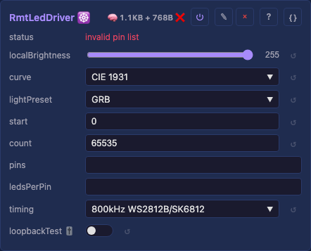 The block every driver card opens with, shown here on RMT LED. Added once by DriverBase so no driver re-implements it: a per-driver output correction (how this driver's slice looks) and a source window (which slice of the shared buffer it reads). A driver card leads with whichever half applies, and its own controls follow. Hue and Preview correct nothing, since the fixture and the browser do it; HUB75, Preview, NDI and HLS take the whole buffer rather than a window. |
localBrightness — this driver's dim (0–255), multiplied with the global brightness.curve — brightness to output: CIE 1931, gamma 2.2, gamma 2.8, or linear.lightPreset — the light preset applied per light, for order and white.whiteMode — how W is derived, shown when the preset carries a W channel.start — first light of the shared buffer this driver reads (default 0).count — how many lights from start. Blank drives all of them.Tests: none yet API: reference Details: Shared, details |
LED drivers
| Module | Details |
|---|---|
| RMT LED 💫 · wire Addressable WS2812B-class LEDs on a handful of strands, clocked by the chip's RMT peripheral. The classic choice, and the one that needs no DMA peripheral: for more than a few strands see Parallel LED below. What the peripherals buy is in the details below. Plus the shared controls above: |
pins — data GPIO list: 18,17,16, or ranges like 20-23, mixed freely. Empty idles until set.ledsPerPin — lights per strand. Blank splits evenly, one number to all, a list per strand.timing — the wire bit rate. A 12V WS2811 needs 400kHz; the default suits the rest.t0hNs / t1hNs / periodNs — the bit timing itself, shown when timing is custom.🔧 loopbackTest — a TX to RX self-test, verdict in the status field.🔧 loopbackTxPin / loopbackRxPin / loopbackFrame — its pins, and whether a whole frame is sent.Tests: RMT API: reference Details: none yet |
Parallel LED 💫 · wire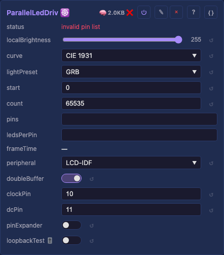 The same LEDs, up to 16 strands clocked out at once by a DMA peripheral, which is what makes a large wall possible. Which peripheral drives the bus, and what each buys, is in the details below. Plus the shared controls above: |
pins — data GPIO list: 18,17,16, or ranges like 20-23, mixed freely. Empty idles until set.ledsPerPin — lights per strand. Blank splits evenly, one number to all, a list per strand.peripheral — the DMA peripheral, filtered to what the chip supports. It divides the card.doubleBuffer, pinExpander, latchPin, bus pins — shown per peripheral.read-only frameTime — what one frame costs on the wire, the headroom the pipeline has left.🔧 loopbackTest — a TX to RX self-test, verdict in the status field.🔧 loopbackStrand / loopbackIntrusive — which strand it tests, and whether it may disturb output.Tests: shared + peripherals API: reference · peripherals: i80 · MoonI80 · Parlio Details: Parallel LED, details |
HUB75 🟦 · panels on your own pins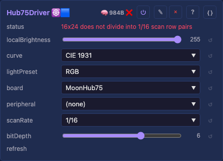 Drives HUB75 LED panels straight from the board's GPIO, with no receiving card in between. The sibling of Panel Card, which drives the same panels over Ethernet instead; which one a wall wants is a size question, answered in the details below. New, and not yet run on a wall we own. Built from the panel's documented behavior with its encoder pinned by host tests, which is not hardware verification. Reports welcome: refresh plus your geometry is what makes one useful. |
board — the wiring to use; picking one fills in the fourteen pins.r1 g1 b1 / r2 g2 b2 — the six color lines, upper half-panel and lower.a b c d e — the row address. d on 1/16 panels, e on 1/32.clk lat oe — shift clock, latch, output enable.peripheral — LCD_CAM or Parlio, where the chip has both and the frame fits.scanRate — 1/8, 1/16 or 1/32, read off the panel, not calculated.bitDepth (2 to 4) — color precision against refresh and memory.clockEdge — rising or falling. Every pixel one column over means the other one.refresh — the measured rate. The number to report if a panel flickers.Tests: none yet API: reference · encoder: Hub75Slots Details: HUB75, details |
Network drivers
| Module | Details |
|---|---|
Network Send 💫 · UDP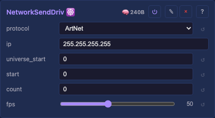 Streams the buffer over UDP as Art-Net, E1.31 / sACN or DDP, one burst per frame, to Falcon/Advatek controllers, xLights and LedFx. Feeds several receivers from one driver, each its own slice. Mixed DMX fixtures and the addressing rules are in the details below. |
protocol — Art-Net / E1.31 / DDP / E1.31 multicast (default Art-Net); the port follows.ips — the receivers, a range or a list: 192.168.1.70-74. Blank idles rather than sending.lightsPerIp — lights per receiver. Blank splits evenly, one number to all, a list each.universe_start — first universe for Art-Net / E1.31, restarting per receiver. DDP ignores it.fps — frame-rate limit (default 50, 1–120).Tests: Network Send API: reference Details: Network Send, details |
Panel Card 💫 · raw Ethernet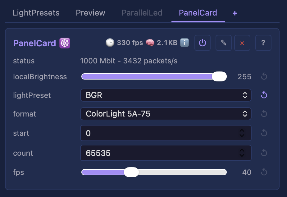 Streams the buffer to ColorLight 5A-75 receiving cards as raw Ethernet, taking the place of the sending card that normally feeds them. The board renders and sends, so it replaces a host PC driving the same wall. The link requirement and the protocol lineage are in the details below. |
format — the card's wire format (ColorLight 5A-75).firmware — v12 and older (default) or v13 and newer. Wrong, and the wall barely updates.No geometry controls — the wall comes from the Layout, cut into card rows.interface — which NIC to send from, by adapter name. Desktop only; raw sending needs privileges.fps — frame-rate limit (default 40, 1 to 120).Tests: Panel Card API: reference Details: Panel Card, details |
Smart light drivers
| Module | Details |
|---|---|
Hue 💫 · bridge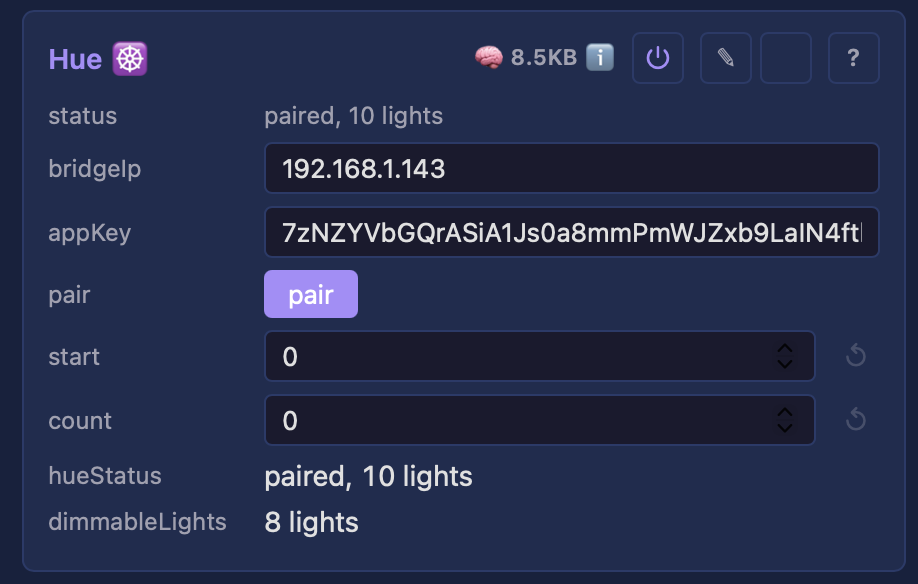 Drives Philips Hue bulbs as pixels: each color bulb in the driver's window becomes one pixel, pushed to the bridge over its HTTP API. Paced to the bridge's ~10 cmd/s limit, so smooth ambient color, not strobing. Up to 32 bulbs, which is a LAN's worth and bounds the driver's memory. |
bridgeIp — the bridge's LAN IPv4.appKey — the Hue app key; filled by pair, persisted.pair — button: press it, then the bridge's physical link button within ~30 s to claim a key.room / light — dropdowns narrowing which color lights are driven (both default All).Tests: Hue API: reference Details: none yet |
Preview drivers
| Module | Details |
|---|---|
Preview 💫 · web UI Streams a true-shape 3D preview to the web UI as a point list, only the real lights at their real positions, so a sphere/ring/arbitrary map shows in its true shape. The one boot-wired driver. It streams on its own WebSocket channel so a large frame never delays the control plane, and only while a viewer is watching. Moving heads show their beam. How the rate and detail trade off is in the details below. |
targetFps — the rate to aim for (default 24, 1–25). Lower for detail, raise for smoothness.Tests: Preview API: reference Details: Preview, details |
NDI 🖥️ · video out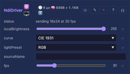 Publishes the layer as an NDI video source, so OBS, Resolume, TouchDesigner or any other NDI receiver picks MoonLight up by name, on this machine or another on the network. Where the Preview driver draws the lights for a person, this hands the same frame to a production tool as video. The grid becomes the frame, one light per pixel, output correction applied, so a receiver sees what the wall sees. Desktop only, and you install the NDI runtime yourself; without it the driver says so and nothing else changes. See the details below. |
sourceName — the name a receiver lists. Blank uses the device's own name.fps — frame-rate ceiling (default 30, 1–120), declared in every frame.Tests: none yet API: reference Details: NDI, details |
HLS 🖥️ · video out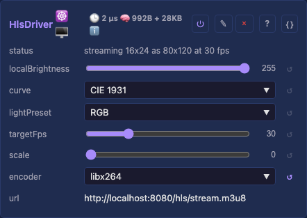 Streams the layer as H.264 over HLS from the device's own HTTP server. Open the url the card shows in VLC or a browser, or hand it to an Apple TV. Where NDI feeds production tools, this feeds anything that plays video. The grid becomes the frame, output correction applied. Latency is HLS's own, 2-5 seconds, so this is for watching rather than live-control feedback. Runs on desktop (you install ffmpeg) and on the ESP32-P4, which encodes in hardware. See the details below. |
targetFps — encode-rate ceiling (default 30, 1–120). Also the bandwidth knob: bitrate is derived.scale — video pixels per light (0 = auto). Each light is a solid block, never a blur.encoder — which ffmpeg encoder (desktop only).read-only — url to play. The card's status line carries state, drops, or why the encoder stopped.Tests: none yet API: reference · the transport-stream muxer Details: HLS, details |
RTSP 🖥️ · video out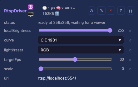 Streams the layer as H.264 over RTSP, which a player pulls rather than fetching segments. Point VLC or ffplay at the url the card shows. It reaches a viewer much sooner than HLS, which buffers whole segments before it plays one, so this is the remote view to reach for. Preview stays the one that keeps pace with the lights, sending raw pixels and no codec at all. Runs on the ESP32-P4 and on the desktop. One encoder, so RTSP and HLS run one at a time. See the details below. |
targetFps — encode-rate ceiling (default 30, 1–60), which is also the keyframe interval.scale — video pixels per light (0 = auto). Each light is a solid block, never a blur.read-only — url to play. The card's status line names the connected viewer.Tests: none yet API: reference · the RTP packetiser · the session Details: RTSP, details |
Shared, details
A lightPreset reference survives some changes and not others. The driver holds the preset's stable id at runtime, so reordering presets never disturbs it, and the reference survives a reboot because the preset's name is persisted and re-resolved on load. The caveat is renaming: within a session the id keeps the link, but after a reboot a renamed preset no longer matches the persisted name and the driver falls back to the default. Re-pick it if you rename a preset a driver uses.
start and count are how several drivers share one buffer. Blank count drives every light; a number drives only that slice. An onboard status LED takes start 0, count 1 while the main strip runs from start 1, both reading the same buffer.
Parallel LED, details
doubleBuffer: leave it on. The driver encodes the next frame into a second DMA buffer while the current one clocks out, so a tick costs max(encode, wire) rather than encode + wire. Measured on a P4 at 16x256 lights it lifted the whole board from about 48 to 76 fps, moving a 7.7 ms wire into background DMA. It costs one extra DMA buffer and one frame of output latency, roughly 8 to 20 ms, which sits inside the perceptual audio-to-visual window and is small next to the wire itself. There is no setup, audio-reactive included, that should turn it off for latency. A board whose second buffer will not fit degrades to the synchronous path on its own.
The 74HCT595 pin expander is experimental and size-limited. Each data pin feeds one '595, so the driver drives pins x 8 strands. It buys pins, not memory: the register is serial-in, so presenting 8 bits costs 8 shift cycles and the DMA frame grows eightfold, about 1.1 KB per light. Above roughly 96 lights per strand that frame exceeds internal DMA RAM. The i80 peripheral is capped there, because above it the frame falls to PSRAM, which the S3's GDMA cannot sustain at the expander's 26.67 MHz clock. MoonI80 lifts that with a streaming ring and drives 128 lights per strand reliably; past 128 a residual refill race still stalls it. The ceiling is 64 strands, set by the encoder's 64-bit active-strand mask. Full status and the measurements: the analysis.
Wiring the loopback jumper through a '595. In direct mode you jumper a data GPIO straight to loopbackRxPin. In shift mode a data GPIO carries the serial stream into the register, not pixel data, so the wire must come from a register OUTPUT. Strand S sits on data pin S / 8's register at shift position S % 8. A '595 shifts MSB-first, so position p appears on output Q(7 - p), and strand 0 is Q7. Set loopbackStrand to the strand whose output you tapped. Walking it 0 to N-1 until the test passes identifies the strand empirically. The '595 runs at 5 V and an ESP32 GPIO is not 5 V tolerant. Use a divider (1 kOhm from the output to the GPIO, 2 kOhm from the GPIO to ground) or a level shifter. Without one the pin can be damaged. No continuity pre-check runs in shift mode, so a mis-wired jumper shows as a bit failure rather than "jumper not detected".
Whose work this is. The clockless I2S / RMT / Parlio techniques come from hpwit (Yves Bazin), whose work is why a single board can drive dozens of parallel strands at all (analysis), on WS2812B prior art from FastLED and WLED.
Which one do I want?
| Want | Use |
|---|---|
| A few strands, any ESP32 | the RMT driver, the simple default |
| Many strands, up to 16 | Parallel LED on i80, the proven scale path |
| Up to 16 strands on a P4 | Parallel LED on Parlio, which needs no clock pin |
| More lights than one DMA buffer holds, or more strands than you have GPIOs | Parallel LED on MoonI80 |
Start with i80. Choose MoonI80 only when you hit one of those two limits: it drives the same pins the same way, streams the frame instead of holding it whole, and can drive a 74HCT595 pin expander so 6 pins reach 48 strands. Both are peripheral choices on the one Parallel LED driver, so switching is a control change on one board with no reflash.
Where each one runs.
peripheral |
Chip | Strands |
|---|---|---|
i80 |
S3, P4, S31, and the classic ESP32 | 1 to 16 |
MoonI80 |
S3, P4, S31 | 1 to 16, or 8 per pin through an expander |
Parlio |
P4 | 1 to 16 |
RMT is its own driver rather than a peripheral, and runs on any ESP32: one strand per RMT channel, which is 8 on the classic and 4 on an S3 or P4.
Two limits worth knowing before you wire. On the classic ESP32 the i80 bus cannot reach PSRAM, so it caps at 2,048 lights; on the LCD_CAM chips it reaches PSRAM and caps at 16,384. Past the cap the driver idles with a status rather than crashing. And MoonI80's streaming ring is wall-proven for frames that fit its buffer pool, while the longest strands have a known last-row sparkle, tracked in the backlog.
Lane, pin, strand. A lane is one bus data line, a strand is one chain of LEDs. Wired directly, one pin is one lane is one strand. Through an expander each data pin feeds one '595 and fans out to 8 strands, so 8 data pins reach the driver's ceiling of 64.
How the frame is built, the DMA each peripheral programs, and the expert ring* tuning are on the API pages: Parallel LED, i80, MoonI80, Parlio, RMT, slot encoder.
Network Send, details
Unicast is the default because Art-Net 4 requires it and because broadcast makes every host on the LAN parse every packet. A broadcast address still works if you type one. E1.31 multicast sends to sACN's own per-universe group (239.255.{universe_hi}.{universe_lo}) rather than the configured address, so one send reaches every receiver that joined that universe. It is opt-in rather than the default, because the saving only materializes on a switch that does IGMP snooping and firmware cannot tell. See multicast and IGMP snooping.
A DMX chain of MIXED fixtures needs one driver per fixture type. lightsPerIp splits a window between receivers that share one preset, so it cannot describe a chain where the fixtures differ. Add a driver per type instead, each reading its own start/count slice of the same buffer with its own lightPreset. Two moving-head types followed by RGBW pars is three drivers:
| driver | window | fixtures |
|---|---|---|
| A | start 0, count 2 |
the two big pan/tilt/zoom heads |
| B | start 2, count 4 |
four smaller pan/tilt heads |
| C | start 6, count 10 |
ten RGBW pars |
Each maps its slice onto that fixture's real channels, so differing channel counts and orders are fine, and each carries its own universe_start. The layout must hold every light, 16 here, since the windows are slices of one shared buffer.
Two consequences of motion channels being a property of the LAYER rather than of a driver:
- Order matters when the motion ROLES differ, which is why the table puts the pan/tilt/zoom heads first. The layer's motion slots come from the first enabled driver whose preset carries motion, so the richest fixture has to lead. Swap A and B and the zoom has no slot at all, so those heads never zoom. Fixtures differing only in channel count or order are unaffected.
- Every light carries the motion bytes, used or not, so a mixed rig's buffer is as wide as its widest fixture. Memory rather than correctness: a par's
Correctiondiscards the aim.
An effect writes setPan for every light in its layer, so a formation spanning the window treats the pars as rig positions too. Use separate Layers when the heads should move independently.
Panel Card, details
These cards need a 1 Gbit link, not for bandwidth but for wire time. A 256x256 panel at 40 fps is only about 65 Mbit/s, but the cards have no buffering and latch on the sync frame, so a whole frame must arrive inside the inter-frame window. At 100 Mbit the same bytes take ten times as long, which breaks that timing and shows as tearing or wrong rows rather than as an error. The driver reads the negotiated speed and warns, but still sends: a small panel may be fine, and a measurement beats a refusal.
No IP is involved, no address, no port, no DHCP, so the driver works on a link that never got a lease. A row wider than 497 pixels goes out as several packets.
The interface dropdown lists DETECTED adapters, friendly names on Windows via Npcap and kernel names on Linux and macOS, re-listed on every control change so a hot-plugged NIC appears. The choice is remembered by adapter name rather than by index, so it survives reboots and Npcap reinstalls. none (capture only) records frames without sending. Raw sending is privileged: root or CAP_NET_RAW on Linux, BPF access on macOS, Npcap or WinPcap on Windows; without it the driver records frames instead and says so. Step by step per OS: Driving LED panels with a receiving card.
Card firmware. v13 and newer act on the second copy of the brightness and sync frames, so both are sent twice; v12 and older act on the first and take a second sync as another latch. Reading and changing a card's version: the tutorial.
Protocol references: FPP's ColorLight-5a-75.cpp is the implementation this driver's byte layout agrees with. Harald Kubota's 5A-75B protocol write-up documents the same wire format independently, including the brightness and color-temperature bytes and the discovery exchange.
Read the write-up with its comments: a reader supplied the controller-number field that makes multiple cards on one segment distinguishable. The article's own MAC pair is printed the other way round from FPP's (destination 11:22:33:44:55:66, source 22:22:33:44:55:66, which is what this driver sends and what the cards filter on). Its lineage runs back to the original mplayer-colorlight reverse engineering.
HLS, details
On desktop you install ffmpeg yourself (any 5.x+, on PATH), because MoonLight never ships or links an encoder. Install it with brew on macOS, winget on Windows, or apt on Debian, Ubuntu and Raspberry Pi OS. Without it the driver reports ffmpeg not found and nothing else changes.
The encoder control picks which one ffmpeg uses: libx264 (the default, in practically every build) is software.
Three hardware encoders offload it instead, and are worth picking on large grids: h264_videotoolbox on a Mac (~10% CPU for a 1024x1024 stream on Apple Silicon), h264_v4l2m2m on a Raspberry Pi, and h264_nvenc on NVIDIA.
An encoder your ffmpeg lacks starts and exits immediately; the status then reads encoder exited - check ffmpeg.
On the ESP32-P4 there is no ffmpeg and no filesystem in the path: the chip's own H.264 block encodes and MoonLight packages the MPEG-TS itself. Segments are served from a RAM ring rather than written to flash, which at one segment per second would wear it for nothing. The encoder control is absent, since the hardware offers only one.
Sizing the picture. The P4's encoder takes only EVEN dimensions between 80x80 and 1920x2032, so an odd wall has its scale doubled so both axes come out even. A wall whose scaled size exceeds the maximum is refused with a status rather than streaming something the hardware cannot encode. Desktop ffmpeg has none of these limits. The floor is what the auto scale exists for: the P4 will not accept a frame smaller than 80x80, and a small wall streamed 1:1 arrives as a postage stamp in the player. scale at 0 (the default) therefore picks the smallest whole factor that lifts both axes to 80: a 20x10 wall streams as 160x80 rather than being refused, and a wall already past 80 stays 1:1. One factor serves both axes, so the aspect ratio is preserved and each light stays a square block. Raising scale by hand on an already-large wall costs real time (a 128x128 wall at scale 4 measures about 60 ms per frame against 1 ms at 1:1) and buys nothing a player's own zoom does not.
The bitrate is derived, not a setting. It follows from the grid size and targetFps at about 0.1 bits per pixel per frame, which puts a 512x512 wall at 30 fps near 800 kbit; a 128x128 lands under the 500 kbit floor the derivation clamps to. targetFps is the knob for bandwidth, and the better trade for LED content: fewer frames rather than a blockier picture.
Where the segments live. On desktop, the transient /.hls/ directory, served at /hls/ and excluded from config backups. Large grids trade framerate, the render loop being single-threaded: 512x512 streams smoothly, TV-native resolutions do not yet.
RTSP, details
Playing the stream. Any RTSP player opens the url the card shows. These two are what the driver is tested against:
-fflags nobuffer -flags low_delay is what makes ffplay show the stream as it arrives rather than filling a buffer first, which is the whole point of reaching for RTSP. VLC buffers about a second by default, so --network-caching=100 brings it closer.
Watching LEDs on a monitor. A grid is small in pixels and large in meaning, so scale it up with nearest-neighbor and each light stays a crisp square instead of a blurred blob:
ffplay -fflags nobuffer -flags low_delay -probesize 32 -analyzeduration 0 \
       -vf "scale=768:768:flags=neighbor,format=yuv420p" rtsp://<device>:554/
-probesize 32 -analyzeduration 0 skips the startup probing, so the picture appears at once. format=yuv420p silences ffplay's No accelerated colorspace conversion notice, which reports a missing SIMD path in the player's own window conversion and says nothing about the stream.
The newest viewer is the viewer. One session plays at a time, since each viewer costs another send on a device that is also driving lights. A new connection takes the session over rather than being refused. The reason is that a player which vanishes without TEARDOWN leaves a socket open and silent, and TCP reports a peer's absence only to a write it stops acknowledging, so waiting on that would strand the stream for minutes. The displaced viewer sees its connection close, which every player reports.
UDP carries the video. The control conversation runs over TCP on port 554, and the frames go to the UDP port the viewer names in SETUP. A network that blocks that port pair leaves the stream silent while the session looks connected. A player asking for interleaved TCP instead is told so by code, since this server speaks UDP.
The rate is what the device renders. targetFps is a ceiling rather than a promise: a heavy effect that ticks at 8 fps is streamed at 8 fps, since a frame that was never rendered cannot be sent. A stream slower than expected is therefore a question about the render loop rather than the transport. Each module's own tick time in the UI says which effect is spending the time.
The delay that remains is the codec's. H.264 emits a frame once it has the whole frame, and a decoder holds one more, so tens of milliseconds stay whatever the transport does. What RTSP removes is HLS's segment buffering, which is the seconds.
Preview, details
Close the preview when you do not need it. The device renders preview frames only while the preview pane is open. Dismissing it stops that work entirely, which frees the device for rendering and keeps the UI responsive on a large layout, worth doing while you are editing effects on a big wall.
The preview thins itself out. When the connection cannot carry full detail, the preview shows a regular sample of the lights rather than all, the status reads preview 1/4 and so on. The device reports every frame it had to drop and your browser reacts. Persistent drops trade detail for rate, drop-free stretches earn it back a step at a time, and a step that brings the drops back is undone with growing patience, so a borderline connection settles instead of flickering between sizes. A slow effect drops nothing, so it never costs preview detail. A fast connection previews everything, with nothing to configure.
If the preview looks choppy, it is the connection rather than the device: frames are dropped rather than queued, so the wall itself is never held up by the preview. Lower targetFps if you would rather keep full detail at a slower rate.
NDI, details
You install the NDI runtime yourself, MoonLight cannot ship it. Until you do, the driver reports NDI runtime not installed and everything else works normally.
| OS | Where it comes from |
|---|---|
| macOS | NDI Tools (free). It puts the runtime inside its app bundles rather than system-wide, which MoonLight knows to look for; a Resolume install also carries one. |
| Windows | The NDI Tools or SDK installer puts Processing.NDI.Lib.x64.dll on the PATH. |
| Linux | The NDI SDK. |
To see the output you need a receiver. NDI Video Monitor (part of NDI Tools) is the simplest; OBS gains an "NDI Source" via the DistroAV plugin. MoonLight appears by the name in sourceName, or the device's own name when that is blank.
Desktop only. No NDI runtime exists for the ESP32 chips, so the driver is not offered there. An ESP32 reaches the same tools over Art-Net, sACN or DDP instead, send with the Network Send driver, receive with the NetworkReceive effect.
Status line
| It says | It means |
|---|---|
NDI runtime not installed |
Install it, per the table above |
could not create the NDI source |
The runtime is there but refused, usually a name clash with another source |
sending <w>x<h> at <n> fps |
Live; look for it in your receiver |
HUB75, details
Which of the two HUB75 paths. A receiving card (Panel Card) earns its place above roughly 16,384 pixels. Below that it is a Windows tool to configure and a dedicated Ethernet link to run, for a panel the board could have driven itself. This driver is the small end of that split.
Which silicon. A chip with an LCD_CAM or Parlio block. The classic ESP32 has neither, and is excluded on pins before memory is even a question: it has 13 usable output GPIOs and a 1/16 port needs all 13, leaving nothing for a strand, a button or a microphone.
Where the pins come from. The board select fills all fourteen lines on first use. A published map (MoonHub75, MatrixPortal S3, Waveshare RGB Matrix) hides the pin rows, because those lines are soldered and there is nothing to act on; the generic per-chip sets and Custom show them. Hidden rows stay bound, so the values persist, still drive the panel, and still show in the pin map. A line on a pin the chip has wired to flash or PSRAM is refused before init, with the line named. That is why the MatrixPortal S3 runs the esp32s3-zero image: three of its lines sit on 35-37, which the octal N8R8/N16R8 images hold for PSRAM. Wiring your own: the per-chip free sets are in GPIO usage.
The published board maps. Each is taken from that board's own source, written in this driver's control order (clk, lat, oe). A panel's ribbon numbers its color lines R1/G1/B1 (upper half) and R2/G2/B2 (lower half). Some board docs call the same pairs R0/G0/B0 and R1/G1/B1. That is the one naming trap worth knowing before wiring.
MoonHub75             r1  1   g1  5   b1  6    r2  7   g2 13   b2  9
                      a  16   b  48   c  47    d 21    e  38
                      clk 18  lat 8   oe  4

MatrixPortal S3       r1 42   g1 41   b1 40    r2 38   g2 39   b2 37
                      a  45   b  36   c  48    d 35    e  21
                      clk 2   lat 47  oe 14

Waveshare RGB Matrix  r1  4   g1  5   b1  6    r2  7   g2 15   b2 16
                      a  18   b   8   c   3    d 42    e   9
                      clk 41  lat 40  oe  2
The MoonHub75 PCB is a Lilygo T7-S3 on a passive adapter, designed by Sören (lost-hope). Its map comes from the hardware repository's own README. The same board carries an INMP441 microphone socket on IO10/11/12, so an audio-reactive effect and a panel run together on it. The Adafruit MatrixPortal S3 map is from the board's CircuitPython pins.c. The Waveshare is SKU 34422, not to be confused with the Waveshare ESP32-S3-Matrix, a different product with an onboard 8x8 WS2812 matrix and no HUB75 connector. A 1/32-scan panel needs e; on 1/16 panels that pin is free.
Two controls a panel cannot tell you. scanRate is the panel's own, and two panels of identical dimensions can scan differently, so it is read off the panel rather than calculated from its size. peripheral is yours rather than the driver's: a P4 has one LCD_CAM and one Parlio, so a board already driving WS2812 strips from one needs the panel on the other, and only you know which way round.
How a HUB75 panel works, in two facts. It is scanned, not addressed: two rows light at once, the upper half-panel through R1/G1/B1 and the lower through R2/G2/B2, selected by a row address on A/B/C (and D/E on finer panels). The controller walks every scan row in turn and persistence of vision does the rest, so a 64-row panel has 32 scan rows and row r drives panel rows r and r + 32 together.
And brightness is time, not amplitude. A HUB75 pixel is a switch, on or off, so intensity comes from binary coded modulation: bit plane p is displayed for 2^p time units, and a value lights its planes for a total proportional to itself. That weighting is the peripheral's output-enable window, and it is not built yet, which is why the depth cap below exists. Either way the encoder stores each plane once. Emitting plane p 2^p times is the obvious reading and it is wrong: 255 passes at 8-bit is 1,060,800 bytes for a single 64x64 panel, where storing once is 33,280.
What depth costs, and why it stops at 4. Every bit plane is a full scan, so depth costs refresh and memory linearly, and each slot on the wire is 2 bytes because the address, latch and output-enable lines sit above bit 7 of a 16-bit word. One 64x64 panel at 1/32 scan is 16,640 bytes a frame at 4-bit. The planes are emitted once each rather than weighted for 2^p time, so bit 3 lights as long as bit 0 and a fifth plane would buy nothing the eye can find. The weighting is backlogged, and the cap lifts with it.