Waveshare ESP32-P4-ETH hardware reference¶
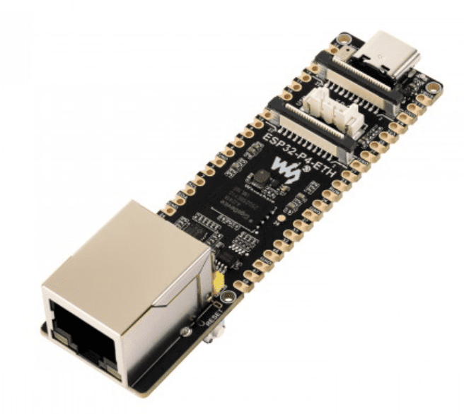
Pin maps and onboard features for the Waveshare ESP32-P4-ETH, read from the schematic so MoonLight work reads this instead of re-scraping the PDF. The board runs the plain esp32p4rev1-eth firmware, the same build the P4-NANO uses, and is "Waveshare ESP32-P4-ETH" in the device catalog.
Sources - Schematic: https://files.waveshare.com/wiki/ESP32-P4-ETH/ESP32-P4-ETH-datasheet.pdf - Board drawing: https://files.waveshare.com/wiki/ESP32-P4-ETH/ESP32-P4-ETH.zip
Same family as the Waveshare ESP32-P4-NANO: ESP32-P4, RISC-V dual-core, the same onboard IP101 Ethernet PHY wiring, and the same CSI/DSI/I2C accessory-bus convention. See gpio-usage.md § ESP32-P4 for the pin map. It carries the same onboard ES8311 audio codec, feeding an SMD mic and a 2-pin JST speaker header. The MHC-WLED ESP32-P4 shield is a different, unrelated P4 carrier board, with RS-485/line-in and no onboard codec.
Audio (ES8311 codec)¶
The onboard SMD mic and speaker header connect through an ES8311 mono codec and an NS4150B class-D amplifier, the same amplifier chip the ESP32-S31 uses. The ESP is the I2S master, driving MCLK.
| Signal | GPIO | Role |
|---|---|---|
| I2S MCLK | 13 | master clock to the codec, 256 × sample_rate |
| I2S SCLK (BCLK) | 12 | bit clock |
| I2S LRCK (WS) | 10 | word select |
| I2S ASDOUT | 11 | mic data, codec to ESP, the record path |
| I2S DSDIN | 9 | speaker data, ESP to codec; wired on the board, playback is not implemented |
| ESP_I2C_SDA | 7 | codec control bus, shared with the CSI/DSI accessory headers |
| ESP_I2C_SCL | 8 | codec control bus |
| PA_Ctrl | 53 | NS4150B amplifier enable; wired on the board, not implemented |
The ES8311's I2C address is 0x18, the hardware default with no address-select strap. The catalog entry configures AudioService's ES8311 codec on these pins, through the board's I2cBusModule. The speaker path (DSDIN, PA_Ctrl) is a separate, unimplemented capability.
Ethernet (IP101GRI PHY, RMII)¶
The board uses the P4 RMII preset, shared with the Waveshare P4-NANO: MDC 31, MDIO 52, PHY reset 51, reference clock 50 (see EthernetModule). The RMII data lines, fixed by the chip and not part of that preset, read from the schematic:
| Signal | GPIO |
|---|---|
| TXD0 | 34 |
| TXD1 | 35 |
| TXEN | 49 |
| RXD0 | 29 |
| RXD1 | 30 |
| RXDV | 28 |
microSD slot¶
Wired on the board and mounted by SdCardService:
| Signal | GPIO |
|---|---|
| D0 | 39 |
| D1 | 40 |
| D2 | 41 |
| CD/D3 | 42 |
| CLK | 43 |
| CMD | 44 |
| VDD gate (pMOS) | 45 |
Other onboard features¶
From the Waveshare wiki: MIPI-CSI (2-lane, OV5647-compatible) and MIPI-DSI (2-lane, 5, 7, 8 and 10.1-inch panels) accessory headers, plus BOOT and RESET buttons. USB-C is native, with D- on GPIO 24 and D+ on GPIO 25, and a UART-bridge variant also exists.