LightCrafter 16 hardware reference
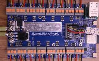
Pin maps and onboard features for the LightCrafter 16, a 16-output LED controller by Mathieu Stephan (limpkin) of Stephan Electronics SàRL, Switzerland.
The board is the SE16 v2 ("SE16V2 / Lightcrafter16"), listed as "LightCrafter 16" in the device catalog.
It runs the esp32s3-n8r8 firmware.
The pins below come from the catalog entry and from the maker's pull requests.
Sources
- Maker: https://www.limpkin.fr, https://github.com/limpkin, Discord https://discord.gg/TC8NSUSCdV
- Contributed by limpkin in https://github.com/ewowi/MoonLight/pull/86 (board support), https://github.com/ewowi/MoonLight/pull/88 (WS2814 white-first), https://github.com/ewowi/MoonLight/pull/89 (voltage and current readout) and https://github.com/ewowi/MoonLight/pull/91 (pins, RS-485, layout, docs, photo)
- Device model LightCrafter 16: mooninstaller/deviceModels.json
- Firmware list: mooninstaller/firmwares.json
- Layout script: moonlive/layouts/lightcrafter16.mll
- Performance: performance.md
Module and firmware
The chip is an ESP32-S3 with 8 MB flash and 8 MB octal PSRAM.
The matching MoonLight firmware is esp32s3-n8r8.
The N16R8 image overruns the 8 MB flash.
LED outputs
The board has 16 LED outputs, driven by the parallel LCD (LCD_CAM i80) driver with one lane per output. The data pins, in output order 0 to 15:
47, 21, 14, 9, 8, 16, 15, 7, 1, 2, 42, 41, 40, 39, 38, 48
The order follows the board layout.
Outputs 0 to 7 run along one edge, then outputs 8 to 15 run back from 7 to 0 along the other edge.
X0Y0 is the top left corner, next to the Ethernet connector.
The lightcrafter16.mll layout script places the lights in that order.
The catalog entry sets the driver's two unused signal lines to clockPin 19 and dcPin 20.
Those are the S3's own USB data pins, so a USB device on that port and this choice exclude each other.
A long LED encode on core 0 starves the W5500 network stack, so the encode runs on core 1 (see performance.md).
The strips used in practice are SK6812 RGBW.
The board runs the StadBeest legs, 10 SK6812 RGBW strips of 144 lights (see multi-board installation).
A brown-out at high brightness on the StadBeest came from the wiring resistance of its power feed.
In a test setup fed through speaker cable too thin for the load, power.mls read 4.7 V at 0.5 A and 3.3 V at 18.4 A.
Ethernet (WIZ850io, W5500 over SPI)
Ethernet comes from a WIZnet WIZ850io module carrying a W5500, connected over SPI.
| Signal | GPIO |
|---|---|
| MISO | 13 |
| MOSI | 11 |
| SCK | 12 |
| CS | 10 |
| INT | 45 |
| Reset | 3 |
GPIO 3 must be driven high. The WIZ850io holds its own reset until then. The same line also enables the RS485_DE, VBUS_DET and W5500 INT signals and drives an LED.
RS-485
| Signal | GPIO |
|---|---|
| TX | 17 |
| RX | 18 |
| DE | 46 |
MoonLight leaves the RS-485 port unused.
Infrared receiver
The infrared receiver is on GPIO 4 and is read by the InfraredService.
Power sensing
The board measures its input voltage and input current on two ADC pins.
The power.mls service reads both and shows volts and amps on its card, in tenths.
It only shows them: acting on them, such as dimming when the voltage sags, is planned.
| Quantity | GPIO | Circuit | Conversion |
|---|---|---|---|
| Input voltage | 5 | Divider of 10k and 1k43 | volts = adc_mV × 11.43 / 1430 |
| Input current | 6 | Hall sensor, 40 mV/A, 0.5 V quiescent output, behind a divider of 10k and 5k1 | amps = (adc_mV − 330) × 37.75 / 1000 |
USB
GPIO 0 detects VBUS on the S3's native USB port, which uses GPIO 19 and GPIO 20.
A USB-to-serial bridge on UART0 (GPIO 43 and 44) is what the bench uses for flashing.
It enumerates as /dev/cu.usbserial-*.