Core services
The user-added Service modules — capability bridges the device provides or consumes, added and removed at runtime in the Services container (the core-domain twin of the light domain's Effects/Drivers). Fixed device infrastructure (identity, network, inspection tools) lives under System — see core/system.md. Every row links to its generated technical page (the full API, from the .h) and its tests.
Services
The top-level container the Service modules hang under — a grouping node with no controls of its own, the same shape as Effects/Drivers in the light domain. Adds/removes its children (Audio, OSC, Infrared, Button, Analog, MoonLiveService) at runtime via the generic module machinery.
Detail: technical
| Name | Preview | Controls | Links |
|---|---|---|---|
| Audio A Service (added by the user, not auto-wired): the audio source that feeds the FFT audio-reactive effects consume via AudioService::latestFrame(). mode is the first choice, the module's identity, and each mode shows only its own detail controls: Local audio runs its own input (an I²S microphone or line-in ADC on boards; an OS capture device on desktop) and analyzes it locally, Receive network is a pure network sink a peer's WLED-compatible audio drives, and Simulate is a synthesized source for demos and tests. On I²S targets Local mode idles until real GPIOs are entered; on desktop it captures the picked device right away. A desktop in Local mode with send audio on is a WLED audio-sync source: one machine's microphone or loopback drives a whole fleet of boards in Receive mode. The Receive network mode and every network-sync control (send audio, syncPort, sync status) exist only on network-capable targets (platform::hasNetwork); a no-network build offers a two-option picker: Local audio and Simulate. Capturing what the machine plays (loopback), per OS. macOS has no native loopback: install BlackHole, create a Multi-Output Device in Audio MIDI Setup (tick your speakers/DAC first plus BlackHole, enable drift correction on BlackHole) and set it as the system output; the speakers keep playing while an identical copy lands in BlackHole, which this control captures. The Mac's volume keys go dead on a multi-output device: set volume in the player or on the DAC. Windows usually needs nothing: enable Stereo Mix (Sound settings, Recording tab) and pick it here; it taps the output while the speakers keep playing (VB-Cable is the fallback where a driver lacks Stereo Mix). Linux PulseAudio/PipeWire expose a Monitor of source natively; just pick it. |
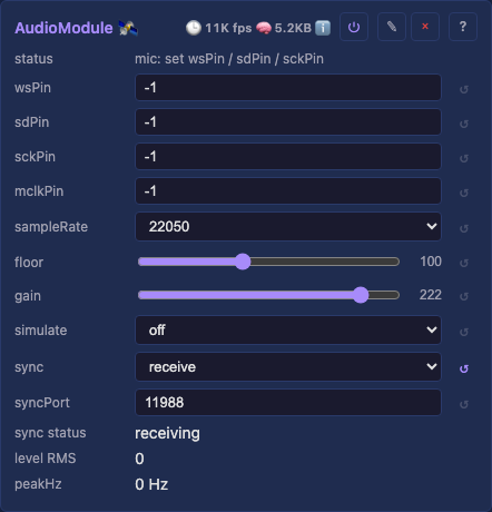 |
mode — Local audio / Receive network / Simulate: analyze the on-board mic/line-in, consume a peer's audio off the network (WLED-compatible), or feed a synthesized signal. Receive network appears only on a network build; the controls below are its detail, shown per mode.micMode: (Local, I²S targets) I2S for a three-wire part (the INMP441 and most MEMS mics, and line-in ADCs), PDM for a two-wire one (a clock and a data line, as on the QuinLED Dig-Next-2's onboard microphone). PDM uses wsPin as its clock and sdPin as its data, and hides the two clock pins it does not have.sckPin / wsPin / sdPin: (Local, I²S targets) the I²S GPIOs (bit clock / word-select / data; unset until entered).mclkPin: (Local, I²S targets) master-clock GPIO for a line-in ADC that needs one (e.g. the PCM1808); leave unset for a plain mic.device: (Local, desktop) the OS capture input: default follows the system setting; loopback devices appear when present, so effects can follow what the machine plays. Picked by list position: if the OS reorders devices, re-pick (default is order-stable).sampleRate — (Local) mic/ADC sample rate.levels — (Local) who sets the display window: manual, the floor and gain sliders, or automatic, a learner that measures each band's own floor and typical loudest level and maps that range onto the window. Automatic is what makes a treble band read level with a bass one under spectrally balanced material, instead of sitting at a fraction of it. The choice picks which controls below are shown, so the mode is one decision rather than four interacting sliders.floor: (Local) the silence threshold, in both modes: below it a band reads zero and, in automatic, the learner does not learn from it. That second half matters as much as the first, because a learner that studies an empty room maps its noise floor onto the whole display and shows a silent room at full scale. Raise floor until a quiet room reads still. It is the one setting that depends on the part and the room, so it is the knob to reach for first, and the only one automatic mode exposes.gain: (Local, manual) the width of the display window: higher is a narrower window, so the display runs hotter. It sizes the band window directly and scales the level's own window, which is wider because a block RMS covers more dB than a single frequency bin's peak. The default suits a quiet MEMS mic; a loopback device delivers near-full-scale digital audio, so turn gain down hard (single digits) or everything clips to maximum.send audio — (Local, network build) send the local analysis as WLED audio-sync packets for the WLED ecosystem.simulate — (Simulate) the synthetic pattern: music (a plausible song) or sweep (a deterministic band-marching test pattern).syncPort — (network build) the UDP port (default 11988, the WLED standard), shown when sending or receiving; set it the same on both ends. sync status reports the live send/receive state.read-only — level (RMS), peakHz (the audio driving effects, from any source). |
Tests Technical ⌄ details |
| OSC Receives OSC over UDP and writes it onto this device's controls, so a fader in Resolume, TouchDesigner, TouchOSC or a DIY Arduino-over-Ethernet rig drives projectMM directly. It owns no surface of its own: everything lands in the same control writes the HTTP API and the UI use, so every validator still runs. controls, on the same LAN-trust basis as the Art-Net and audio-sync receivers, so it is a capability you turn on rather than one every device carries. Feedback: the device answers. With feedback on, a control that changes anywhere (the web UI, a preset recall, an audio-reactive effect) is mirrored back to the surface, which is what keeps a client honest and what moves a motorised fader. feedbackTo names the receiver, or is left empty to answer whoever last wrote to us; feedbackPort is where that client LISTENS, which is not the port we listen on (Open Stage Control calls its own osc-port). A client learns the current state three ways: when it first writes to us from a new address, when its address changes, and whenever it sends /mm/hello. The last one exists because a client restarting on the SAME address is invisible to the other two, and most controllers send nothing of their own on load, so every widget would show its layout file's defaults until the user moved one. The shipped session has a sync from device button for exactly this. Setting one up, from installing the app to using it from a phone, is its own page: Driving projectMM from a phone or tablet. It needs no checkout and no tooling, just the app and the session file from the latest release. |
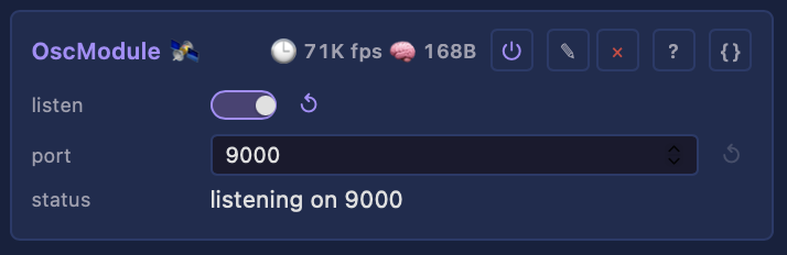 |
listen — receive OSC (default off). This opens an unauthenticated UDP port that writesport — the UDP port (default 9000, what TouchOSC uses). Applies live.status — listening, off, or why the port could not be opened. |
Technical ⌄ details |
| Infrared A Service (added per board): an infrared remote receiver whose rows map learned codes onto other modules' controls, through the shared Scheduler::setControl primitive. A remote press and an OSC message are indistinguishable to whatever they drive. A row is the binding. There is no fixed set of actions: a remote has twenty keys, so it has twenty rows, each learned and each pointing wherever you want. Set a row's learn and the next code received binds to it, which is how any remote works without a shipped code table. Arming one row disarms any other, so a code cannot bind twice. A fresh service starts with no rows. Add one, learn a key, pick a target. |
— | pin: the receiver GPIO (unset until entered; on the SE16 it shares GPIO 5 with the Ethernet MISO via the board switch, on the LightCrafter it is its own GPIO 4). The status line reports whether the channel actually opened, not merely that a pin is set.codes: the mapping rows. Per row: code (the learned frame, editable as hex so a code read elsewhere can be typed), learn (arm this row for the next frame), and the shared target fields below. |
Technical |
| Button A Service (added per board): a list of buttons, each on its own GPIO, each driving a control through the same Scheduler::setControl primitive the infrared service uses. A press and a UI click are the same thing to whatever they drive. A list because boards have more than one: a QuinLED Dig-Next-2 has three, a stage rig has a pedalboard. A foot pedal needs no module of its own: electrically it is a momentary switch on a jack, so it is a row with kind = set. #### What a row targets Both services share these three fields, because what happens after an input fires is the same whichever input fired it: Only a set row acts on the release. A toggle or a delta acting on both edges would fire twice for one push. |
— | debounceMs: how long a level must hold before it counts as a real press. Debounced here rather than in the platform layer, because a bouncing contact is a property of the switch. Polled at 50 Hz: a contact closes for tens of milliseconds.buttons: the rows. Per row: pin, activeLow (on for the usual wiring, a switch to ground with an internal pull-up; off for a switch feeding 3V3), a live pressed readout so you can see a button work before binding it, and the shared target fields below.target: Module.control. Pointing at Control.switch1 puts the input on the control surface, where OSC, MQTT and the web UI reach the same switch; pointing at Drivers.on drives that control directly. The surface is the recommended path, not a rule.kind: toggle reads the target and writes its inverse (a light switch); set writes value while held and 0 on release (hold-to-activate, a pedal); delta adds value, clamped to the control's own bounds (a brightness nudge, a palette step). set is Button-only: it needs a release to write the 0, and a remote reports a press with no release, so an infrared row uses toggle or delta.value: what set writes, or the signed nudge delta applies. Unused by toggle. |
Technical |
| Analog A Service (added per board): a list of ADC pins, each driving a control with a value rather than an event. The continuous twin of Button, which drives the same controls from a contact. An expression pedal is the shape this is built around, and it is why a row carries more than a pin. A pedal's usable travel is never the full sweep: it rests at some count and tops out well below full scale, so a raw reading mapped straight through gives a control that never reaches either end and jumps at one of them. The travel is mapped into the control's own range, so a pedal is configured once and works on any target: a Select with five options takes 0..4, a bool takes on and off. A row pointed at a pad does nothing, because there is no sensible reading of a pedal held at 40% of a preset. Reversed inMin/inMax means inverted, rather than being an error: calibrating by moving the pedal to each end sets whichever end was reached first. Scripts reach the same hardware with adcRead(pin) and adcMax(), which is the path for a sensor whose mapping is a condition rather than a range. |
— | smoothing: how hard the running average pulls toward each new reading, as a percentage. 100 follows the pin exactly; a low number is a heavy filter that lags. An ADC pin jitters by a few counts even at rest, so some filtering is always wanted.deadband: how far the smoothed value must move, in target units, before the control is written. Without it a resting pedal rewrites its target fifty times a second forever.inputs: the rows. Per row: pin, inMin / inMax (the raw counts the travel actually spans), invert (a pot wired the other way round), live raw and value readouts so a pedal can be calibrated by watching it move, and the shared target fields above. |
Technical |
| MoonLiveService A Service (added per board): a MoonLive script that reads hardware and drives controls. The flexible half of the input story, and the twin of a scripted effect: ButtonService and Infrared are the compiled, shipped paths for the inputs a board is built with, and this is the path for everything else. Why a script rather than another module: a mapping row says "this pin drives that control", which is the right shape for a button and the wrong one for anything with a condition in it. A row cannot say "when the distance drops under 50 cm", cannot hold the state that stops it firing every tick, and cannot choose between two presets. A script can, so a sensor nobody wrote a module for needs a datasheet and eight lines rather than a firmware release. recompiles live; a compile error shows on the status line and the service does nothing until it is fixed. the value the running code reads, so a slider move lands without a recompile. A script runs on tick20ms, the 50 Hz poll, not the render tick: a contact closes for tens of milliseconds and a sensor answers at its own rate, so a heavy script costs its own tick rather than stuttering the lights at the frame rate. What a script can reach: gpioRead(pin) and gpioWrite(pin, on) for digital hardware, adcRead(pin) with adcMax() for analog, and setControl(name, value) for the output, which writes the CONTROL SURFACE and nothing else. That is the same two-step model the mapping rows use, so a script and a row reach a driver by one path rather than two. |
— | script: which .mls file to run, picked from the script library. Naming a different oneEverything the script declares with addControl appears as a real control on the card, bound to |
Technical |
Audio — details
WLED audio sync: what is on the wire
Sending and receiving both use the multicast address 239.0.0.1, which is what WLED's own
usermod does (beginMulticast on both ends). It never uses broadcast, so a broadcast sender is
inaudible to WLED and a receiver that only binds the port never hears WLED. This is a
network-layer address, unrelated to any device grouping.
Port 11988 is the WLED contract, and syncPort defaults to it. The port is configurable for
projectMM peers that want a private stream, but a custom port is no longer WLED-compatible: the
endpoint WLED speaks is 239.0.0.1:11988 specifically.
Multicast is also the better neighbour, with a caveat worth knowing: a switch or access point that does IGMP snooping forwards the group only to the ports that joined it, so the other hosts never see the traffic at all. Without snooping the switch floods it exactly like broadcast, and on WiFi it goes out at the lowest basic rate to every station. So multicast can reduce how many hosts have to process ~40 packets a second, but it does not guarantee it. See multicast and IGMP snooping.
The 44-byte v2 packet is byte-compatible with WLED, with one field that is not yet equivalent:
| field | projectMM | WLED | status |
|---|---|---|---|
sampleRaw / sampleSmth |
level / smoothed level | same | compatible |
samplePeak |
latched beat, 80 ms refractory | same rule | compatible |
| byte 17 | zero | zero (reserved2) |
compatible |
fftResult[16] |
bands, clamped to 254 | constrain(…, 0, 254) |
compatible |
FFT_MajorPeak |
peak frequency in Hz | same | compatible |
FFT_Magnitude |
0..255 internally, x16 on the wire | ~0..4096 | compatible |
The magnitude scale differs, so it is converted at the wire. WLED sends the raw magnitude of
its FFT's dominant bin, scaled so that "the end result is linear and ~4096 max" (its own comment
where it divides the input samples by 16). Its effects then divide that by 4, 8 or 16 depending on
the effect and treat the result as a byte, which is why their thresholds read < 48 squelch and
> 144 full brightness. projectMM byte-scales the peak magnitude to 0..255 instead, through the
same noise floor and gain conditioning as the 16 bands, so one pair of knobs governs the whole
spectrum.
projectMM keeps its own units internally and multiplies by 16 on send, dividing by 16 on receive. The factor is exact rather than a fudge: it is the divisor WLED's effects apply, so our full-scale 255 arrives as 4080, right on WLED's own ~4096 design target, and every effect's thresholds land where they were tuned to. Adopting WLED's range internally was the alternative, and was rejected because that range is an artifact of FFT size and input scaling rather than a specification (WLED's own fallback path admits "no idea if 10000 is a good value"), and importing it would cost the property that one floor/gain pair conditions every value the service publishes, in exchange for resolution the receiving effects discard anyway when they divide back down to a byte.
A received magnitude is clamped to 255, since a real WLED source reaches ~9500 and an unclamped value would drive effects harder than locally analyzed audio ever could.
Prior art: the WLED-MM audio-reactive usermod by Frank (@softhack007), the most-used open-source audio-reactive LED implementation, whose adaptive noise-gate concept the analysis here descends from (analyzed with his permission); and @troyhacks, who reworked that DSP onto Espressif's esp-dsp FFT, the same choice this service makes. The line-in path exists because wladi (myhome-control) supplied the hardware and pinout for the MHC-WLED ESP32-P4 shield: its onboard PCM1808 I2S ADC is what mclkPin is for.
OSC — details
Addresses. These are a public contract: a TouchOSC layout built against them keeps working, so they stay small and boring.
| address | argument | drives |
|---|---|---|
/mm/fader/1 .. /mm/fader/8 |
float 0..1 or int 0..255 | the Control surface's faders |
/mm/encoder/1 .. /mm/encoder/8 |
float 0..1 or int 0..255 | its rotary encoders |
/mm/switch/1 .. /mm/switch/8 |
float 0..1 or int 0..255 | its on/off switch row (nonzero = on) |
/mm/hello |
anything, or nothing | resend every value to the sender |
/mm/control/<Module>/<control> |
float 0..1 or int 0..255 | any control directly |
Both argument forms are accepted because controllers disagree: apps send a float in 0..1, hardware bridges send an int in the target's range. Out-of-range values are clamped rather than ignored, so a controller sending 0..127 does something sensible instead of appearing dead.
Send one from the bench with uv run moondeck/check/send_osc.py <ip> /mm/fader/1 0.75.
Origin: projectMM original
One command to a working surface (with the repo checked out). Install Open Stage Control (free, macOS / Windows / Linux), then:
uv run moondeck/run/run_open_stage_control.py                   # device on this machine
uv run moondeck/run/run_open_stage_control.py --host 192.168.1.42
Open http://127.0.0.1:8088 and the surface is there. On the device, turn listen and feedback
on; nothing else needs configuring, because the launcher passes the session, the send address and
the listen port as arguments rather than leaving them to be typed into a settings panel. The session
itself sends /mm/hello when the page loads, so every widget shows the device's real values straight
away instead of its layout file's defaults, and a browser refresh re-reads them.
It runs headless: a web server rather than a desktop window. That is deliberate. The surface is then reachable from a phone or another laptop on the same network (the launcher prints those URLs), and on macOS it sidesteps the quarantine dialog an unsigned download otherwise raises.
--host / --port |
the device and its OSC port (default 127.0.0.1:9000) |
--listen |
where we receive feedback, the device's feedbackPort (default 9001) |
--ui-port |
the surface's web UI (default 8088; 8080 is projectMM's own) |
--app |
the Open Stage Control binary, when it is not on PATH or in the usual place |
--gui |
also open the desktop window; by default it is the server alone |
The launcher looks on PATH first, then in each platform's default install location. Windows and
Linux are untested: the paths are the ones those installers use, but only macOS has been run. If
it cannot find the app, --app takes the full path and that always works.
A ready-made control surface. A session of the switches, encoders and faders ships as a release
asset (projectMM-control-surface.json) and lives in the repo at
docs/reference/examples/open-stage-control.json.
Editing the layout needs read-only off in the launcher.
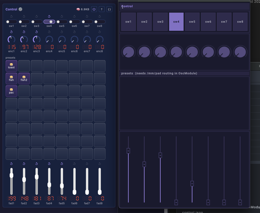
Driving the device from that session, beside the Control card it mirrors.
It binds only to /mm/switch/N, /mm/encoder/N and /mm/fader/N, N being 1 to 8, on purpose. A surface should
address the SURFACE, and Control decides what each one drives, so one layout keeps
working as assignments change and a hardware desk lands on the same bindings. Reaching past it to
/mm/control/<Module>/<control> also works and is the right answer for a one-off, but it hard-codes
into the layout a mapping that belongs on the device. Two have targets today, switch1
(Drivers.on) and fader1 (Drivers.brightness); the rest wait for a target picker.
The session also carries a pad grid, and those pads are inert: /mm/pad/N has no route in the
OSC module yet, so pressing one sends a message nothing reads. It ships anyway because the grid is
the layout a preset launcher wants and the addresses are the ones it will use; treat it as a
placeholder rather than as part of the contract above.
It does not reach a Mackie desk. The X-Touch and QCon Pro G2 speak Mackie Control over MIDI, not OSC: see control surfaces for what would.
Infrared: details
Nothing is fixed in firmware. A row IS the binding: learn a key onto it, pick what it drives from
the target dropdown, and pick whether the press toggles that control, or nudges it by a value. A
handset with twenty keys is twenty rows. set is offered only where an input reports a release, so
it is unavailable here: a remote code is a single event, and a set row would latch the control
with nothing able to clear it.
One key binds to one row. Learning a key that another row already holds moves the binding rather than duplicating it, because dispatch fires the first row holding a code and a duplicate could never run.
The status line reports setup state ("set pin to receive" / "ready"), the learn prompt, a binding ("learned 0x..."), what a press did or why it did not, and an unbound code ("received 0x... (unassigned)").