Layouts
A layout (🚥) tells MoonLight where your lights physically are and how they are wired. Get this right and every effect — from a simple rainbow to a 3D plasma — automatically fits your fixture perfectly.
How layouts work
The coordinate grid
When you define a layout, each light gets a position in a 3D coordinate space (X, Y, Z). MoonLight takes all those positions and figures out the bounding box — the smallest grid that contains every light. Effects are then computed across that whole grid and automatically mapped to your physical lights.
This means:
- Effects are fixture-aware. A plasma effect on a 16×16 panel looks like a full-screen plasma. The same effect on a 3D cube wraps correctly around all three axes. You don't write a different effect for each shape.
- Wiring order doesn't matter to effects. Your LED strip might snake left-to-right on odd rows and right-to-left on even rows (serpentine wiring). The layout describes that wiring pattern; effects just see a clean grid.
- Resolution scales automatically. A 10×10 panel and a 32×32 panel both run the same effects — the effect adapts to however many lights you have.
1D, 2D and 3D fixtures
| Fixture type | Typical examples | Grid shape |
|---|---|---|
| 1D — a line | LED strip, LED bar, single tube | Y axis only — X and Z are 0. The Y axis runs vertically so 1D effects like bouncing balls, drip and rain move in the natural downward direction |
| 2D — a flat surface | LED matrix, panel, ring, wheel | X and Y axes — Z is 0 |
| 3D — a volume | Cube, Christmas tree, spiral tower, Human Sized Cube | X, Y and Z axes all used |
MoonLight automatically detects the dimensionality from the coordinates you define, so 1D effects run on strips and 3D effects light up cubes without any extra configuration.
How effects fill the grid
Effects run across every point in the bounding grid, but MoonLight only lights the positions where your physical LEDs actually sit. The mapping is built sequentially during layout construction:
- The layout calls
addLight(position)once for each LED, in wiring order (LED 0 first, LED 1 second, …). - Each call records which 3D grid position that LED occupies, building a mapping table from virtual grid index → physical LED index.
- After all lights are placed, each grid slot is categorised:
- one light — exactly one LED landed here; effects light it normally.
- more lights — multiple LEDs share the same grid position; all receive the same colour.
- no light — no LED was placed at this grid point; effects compute a colour here but nothing shows it.
There is no nearest-neighbour interpolation — grid points with no LED are simply dark. A 500-LED Christmas tree in a 25×25×100 bounding box has 500 lit grid points and ~62 000 dark ones; the effect wraps naturally around the whole tree volume and every LED shows the colour of its exact position in the grid.
This works best when your fixture has a reasonable pixel density relative to its bounding box. Very sparse fixtures — a handful of moving heads spread across a large stage — would have most of the effect invisible; algorithms optimised for that case are a future addition.
Multiple layout nodes
You can add more than one layout node — for example three separate panels or a ring combined with a bar. MoonLight merges all their positions into a single shared grid and maps effects across all of them together. Lights are assigned to the grid in the order the layouts appear in the node list.
GPIO pin assignment
Layouts also assign groups of LEDs to the ESP32 GPIO pins that drive them. Each layout node controls which pin(s) its lights are connected to. Complex fixtures like a cube or a multi-panel wall often use one pin per face or one pin per panel so each segment can be driven in parallel, improving performance.
Start simple
Not sure which layout to use? Start with Single Row for a strip, Panel for a matrix, or Rings for circular fixtures. These cover the most common setups and are easy to combine into larger builds.
Custom shapes
Any shape that isn't covered by the built-in layouts can be created as a Live Script — a small .sc file with an onLayout() function that places lights exactly where you need them. See Live Scripts.
Future: room-scale mapping
It is possible in principle to treat an entire room or stage as the coordinate space and map all fixtures — panels, moving heads, tubes — into that shared grid. This would let effects flow seamlessly from one fixture to another across physical space. MoonLight's architecture supports it, but algorithms optimised for very sparse, large-scale grids are not yet implemented.
Layout 🚥 Nodes
Below is a list of Layouts in MoonLight.
Want to add a Layout to MoonLight, see develop. You can also create custom layouts as Live Scripts using onLayout(), addLight(), and nextPin().
| Name | Preview | Controls | Remarks |
|---|---|---|---|
| Panel | Defines a 2D panel with width and height Wiring Order (orientation): horizontal (x), vertical (y), depth (z) X++: starts at Top or bottom, Y++: starts left or right snake aka serpentine layout |
||
| Panels | Panel layout + Wiring order, directions and snake also for each panel | ||
| Cube | Panel layout + depth Z++ starts front or back multidimensional snaking, good luck 😜 |
||
| Rings | 241 LEDs in 9 rings | ||
| Wheel | |||
| Human Sized Cube | |||
| Toronto Bar Gourds |  |
 |
|
| Car Lights |  |
 |
|
| Single Column | Choose Single Column for LED strips | ||
| Single Row | |||
| SE16 | Layout(s) including pins for Stephan Electronics 16-Pin ESP32-S3 board see below |
||
| LightCrafter16 | Layout(s) for Stephan Electronics LightCrafter16 ESP32-S3 board see below |
Choosing pins
Choose the right pins with care. See also the IO module to see which pins can in general be used for LEDs (💡). But depending on a specific boards some pins might also be in use already.
Multiple layouts
Single line, single row or panel are suitable layouts to combine into a larger fixture.
Panel — serpentine (snake) wiring
Most commercially made LED matrix panels use serpentine wiring: row 0 runs left-to-right, row 1 runs right-to-left, row 2 left-to-right again, and so on. Without this being accounted for, every other row of your effect would appear mirrored.
The snake checkbox in the Panel controls tells MoonLight that your panel uses this wiring pattern. It corresponds to Wiring::snake[1] (the Y-axis flag) in the layout code (L_MoonLight.h). The snake array has three slots — [0] for X, [1] for Y, [2] for Z — but for a flat panel only the Y-axis snake is relevant and exposed as the snake control.
| Your panel wiring | snake setting |
|---|---|
| Alternate rows reversed (most LED matrix panels) | ☑ enabled |
| All rows run the same direction | ☐ disabled |
If effects look correct on row 0 but every other row is mirrored, toggle the snake checkbox. For 3D cubes (where all three axes can snake independently), the Cube layout exposes snakeX, snakeY and snakeZ controls separately.
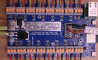
SE16
16-channel LED strip driver by Stephan Electronics
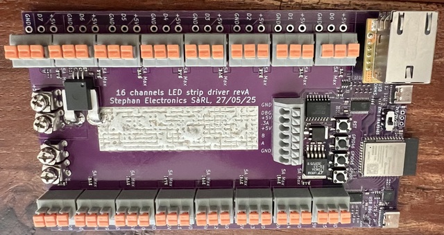
- Leds Per Pin: the number of LEDs connected to each pin
- Pins Are Columns: are the LEDs on a pin a row of the effect (width is 1 (or 2) x ledsPerPin). If not set the LEDs are a column (height is 1 (or 2) x ledsPerPin)
- Mirrored Pins: If set it is assumed that LEDs are connected with increasing positions on 8 pins on one side of the board and decreasing positions on the 8 pins of the other side of the board. The resulting size will have a width of 8 and the height (or width) will be 2 * ledsPerPin. If not set, the width will be 16 and the height (or width) = ledsPerPin
LightCrafter16
16-channel LED strip driver by Stephan Electronics
- Leds Per Pin: the number of LEDs connected to each pin
- Pins Are Columns: are the LEDs on a pin a row of the effect (width is 1 (or 2) x ledsPerPin). If not set the LEDs are a column (height is 1 (or 2) x ledsPerPin)
X0Y0 position is on the top left when the board is positioned in such a way that the Ethernet connector is on the top left.