IO Module

Defines hardware specifics per ESP32 device
- Pins
- I2S
- Switches
- Mods
- Max power
See Board details for info on specific boards
Currently the following boards are defined:

For each board the following presets are defined:
- Modded: set when any pin differs from the selected board preset. Press off to return to the preset defaults.
- Max Power in Watts: adjust the brightness to approach this max power, depending on the number of LEDs used. Default 10: 5V * 2A = 10W (so it runs fine on USB). Used by LED drivers, see Drivers
- Switch1 and 2: If the board contains a jumper or pins have different functions, a custom switch can be set. Eg. select between Infrared and Ethernet. If a switch is turned on or off, the board the modded status will not change. See boards below for details
- Pins: Assign functionality to gpio pins. Other modules and nodes use the pin assignments made here.
- GPIO = gpio_num;
- Usage: See below
- Index: specify first, second, third, ... usage output, e.g. LED D01 to LED D16
- Summary
- Valid (✅)
- Output (💡)
- RTC (⏰);
- Level (HIGH, LOW, N/A)
- DriveCap (WEAK, STRONGER, MEDIUM, STRONGEST, N/A)
Pin usage
- Supported
- LEDs 🚦: Used by LED drivers to setup LED outputs, see Drivers
- Voltage and Current ⚡️: Sets energy monitoring, see System status and System Metrics
- Infrared ♨️: Used by IR driver, see Drivers
- Button LightsOn 🛎️/𓐟: sets on/off in Light Control, Push (🛎️) and Toggle (𓐟)
- Relay LightsOn 🔀: sets on/off in Light Control
- SPI_SCK, SPI_MISO, SPI_MOSI, PHY_CS, PHY_IRQ 🔗: S3 Ethernet, Used by the Ethernet module, see Ethernet
- SDA, SCL: I2C, see below
- High / Low: to indefinitely set high or low a GPIO pin
- RS-485 DE/TX/RX: when all set, for upcoming DMX and RS485 communications
- Planned
- Battery
- I2S for microphone and line in
I2C peripherals

If pins for SDA and SCL are defined, I2C devices will be scanned and displayed here
- Address: The address of a peripheral found
- Name and ID: Unknown if the device is not initialized. If a driver (e.g. IMU driver) is added, it will provide name and ID
Naming convention
- MicroController (MCU): The ESP32 chip (D0, S3, P4, ...)
- MCU-Board (MCB): MCU on a PCB
- Carrier Board (CRB): board that the MCU-board plugs into (Or shield or controller board or interface board)
- Device (DVC): All of the above in a box with connectors
Board details
QuinLed boards
Dig-2-Go, Dig-Uno, Dig-Quad
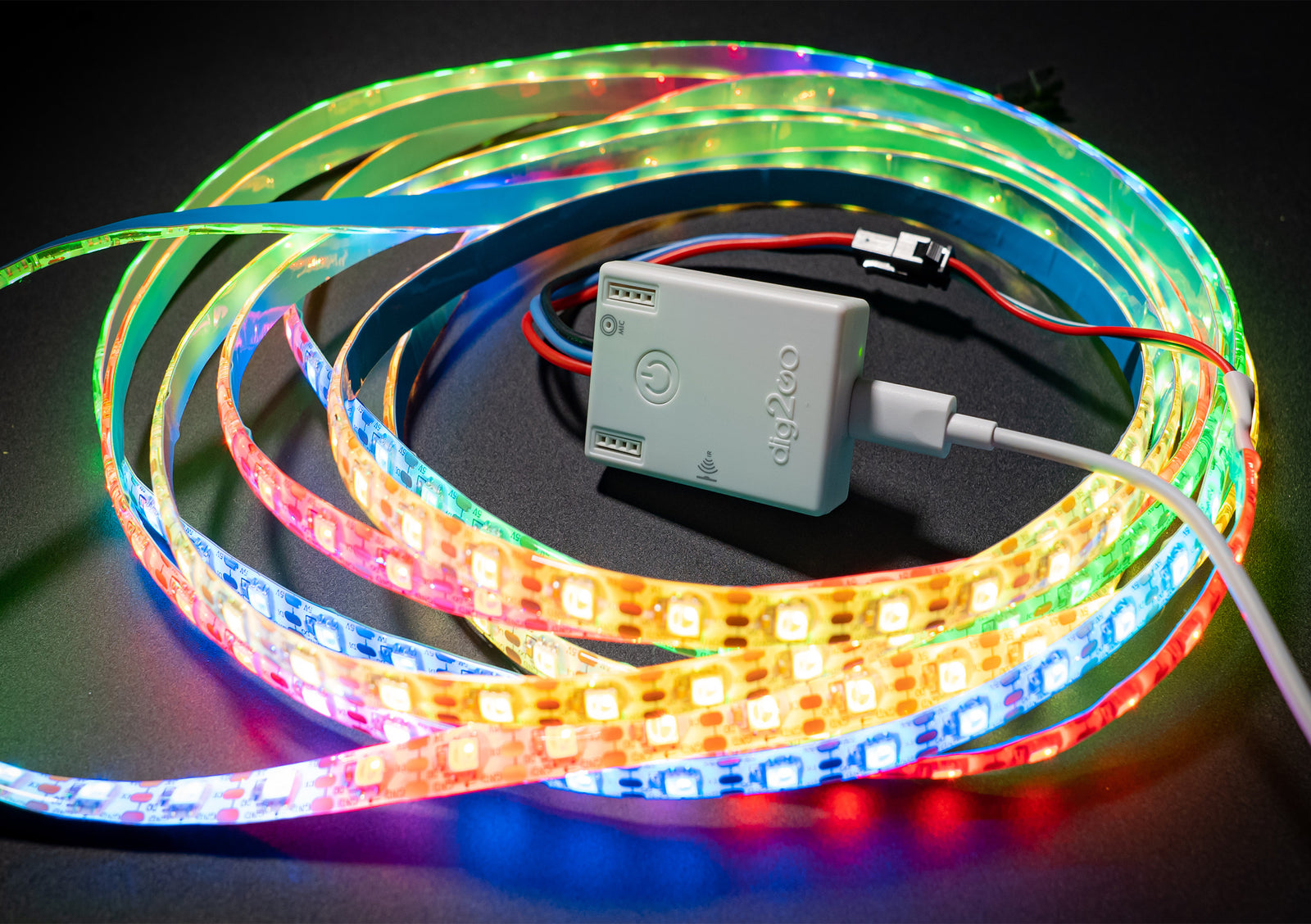

- Dig-2-Go, Dig-Uno, Dig-Quad: Choose the esp32-d0 (4MB) board in the MoonLight Installer
- Dig-2-Go: Shipped with a 300 LED, GRBW led strip: Choose layout with 300 lights (e.g. Single Column for 1D, Panel 15x20 for 2D). Select Light preset GRBW in the LED Driver.
- Currently no OTA support on ESP32-D0 boards: Dig-2-Go, Uno, Quad.
Dig-Next-2

- Dig-Next-2: Choose the esp32-d0-pico2 board in the MoonLight Installer
Dig-Octa

- Dig-Octa: Choose the esp32-d0-16mb board in the MoonLight Installer
- On first install, erase flash first (Especially when other firmware like WLED was on it) as MoonLight uses a partition scheme with 3MB of flash
- After install, select the QuinLED board preset to have the pins assigned correctly.
Reset router
You might need to reset your router if you first run WLED on the same board and no new IP is assigned.
MyHome-Control
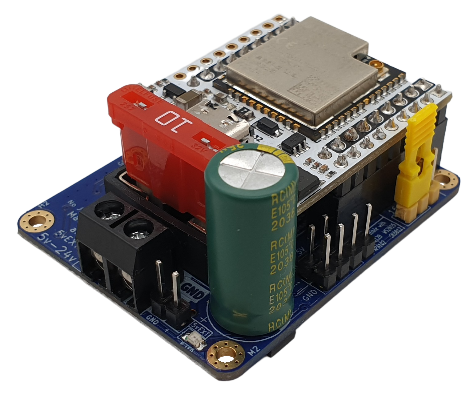
MHC ESP32-P4 shield

- See MHC ESP32-P4 shield. Choose the esp32-p4-nano board in the MoonLight Installer
- On new ESP32-P4 Nano boards, the WiFi coprocessor needs to be updated first to a recent version, currently ESP-Hosted v2.0.17, see the link in the MoonLight Installer
- After install, select the MHC P4 Nano Shield board preset to have the pins assigned correctly.
- Assuming 100W LED power; change if needed.
- Switch1: (also set the switches on the board)
- off (default): 16 LED pins.
- On: 8 LED pins, 4 RS-485 pins and 4 exposed pins
- Switch2:
- off (default): Pins 10, 11, 12, 13 used for build-in Mic over I2S, pin 7 and 8: I2C SDA and SCL
- On: Pins 33, 25, 32, 36 used for Line in, pin 7 and 8: additional LED pins.
- Add the Parallel LED Driver, see Drivers. It uses @troyhacks his parallel IO driver to drive all LED pins configured for the shield.
MHC V57 PRO

- See MHC V57 PRO. Choose the esp32-d0-pico2 board in the MoonLight Installer
StephanElec
SE16 v1

- Choose the esp32-s3-n8r8v board in the MoonLight Installer
- Set Switch1 the same as you set the jumper on the board: off / default: Infrared. on: Ethernet.
- Only 5 boards were ever produced. If you are one of the lucky few, feel free to reach out to limpkin on Discord
LightCrafter16

- Choose the esp32-s3-n8r8v board in the MoonLight Installer
- Documentation to be soon published on limpkin's website